STAIRLab logo
  • Docs 
  • Examples 
  •  

Finite Rotations

3 min read • 482 words

This problem highlights the exceptional accuracy of the ExactFrame formulation for simulating large deformations
On this page
End Moment   References  
Tcl
  • test-e1.tcl
Finite Rotations

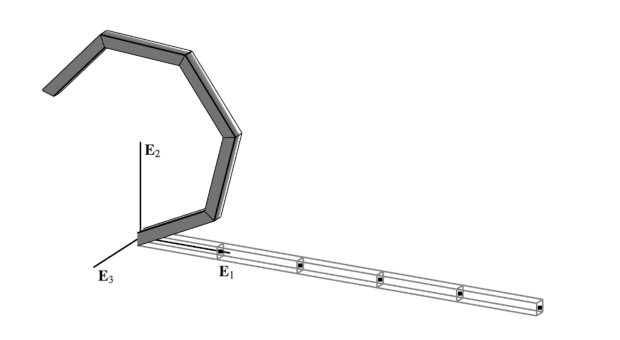
The cantilever beam depicted above is investigated; first under the action of a point moment M\boldsymbol{M} , then a point force F E3F \, \mathbf{E}_3 at its free end ξ=L\xi=L . The reference curve of the reference configuration is given by x0(ξ)=ξ E1\boldsymbol{x}_0(\xi) = \xi\,\mathbf{E}_1 .

In order to simulate this problem with OpenSees the ExactFrame  element formulation is used. This element requires a shear-deformable section, like ShearFiber  .

End Moment  

When F=0F = 0 the configuration is expected to remain in the E1−E2\mathbf{E}_1 - \mathbf{E}_2 plane. Consequently, the out-of-plane director D3\mathbf{D}_3 does not change during deformation so that d3=D3\mathbf{d}_3 = \mathbf{D}_3 . This simplification has two important consequences:

  • There is no distinction between a spatially applied moment M=M d3\boldsymbol{M} = M \, \mathbf{d}_3 and a materially applied moment M=M D3\boldsymbol{M} = M \, \mathbf{D}_3 .

  • The rotation Λ\boldsymbol{\Lambda} becomes vectorial, its variations uΛ(i)\boldsymbol{u}_{\scriptscriptstyle{\Lambda}}^{(i)} at different configurations χ(i)\chi^{(i)} can be added, and the sum of these variations over the course of global equilibrium iterations is equivalent to the logarithmic rotation increment:

    ∑i=0nuΛ(i)≡θ=Log⁡(Λ(n)Λ(0)t). \sum_{i=0}^n \boldsymbol{u}_{\scriptscriptstyle{\Lambda}}^{(i)} \equiv \boldsymbol{\theta} = \operatorname{Log} \left(\boldsymbol{\Lambda}_{(n)}\boldsymbol{\Lambda}_{(0)}^{\mathrm{t}}\right).

In this case, the moment loading can be treated identically for all analyses by simply scaling a constant reference force vector for the node at ξ=L\xi=L :

fM,ref=(00M)t \mathbf{f}_{M,\text{ref}} = \begin{pmatrix} 0 & 0 & M \end{pmatrix}^{\mathrm{t}}

where the reference magnitude M=λ2πEI/LM = \lambda 2 \pi EI/L varies with λ=1/8, 1\lambda=1/8, \ 1 , and 22 for different cases causing the cantilever to loop over itself λ\lambda times. The following parameters are used:

L=10..E=104G=104A=1..I=10−2J=10−2\begin{array}{lcr} L &=& 10\hphantom{..} \\ % ,& A &= 1 \\ E &=& 10^4 \\ % ,& I &= 10^{-2} \\ G &=& 10^4 \\ % ,& J &= 10^{-2} \\ \end{array} \qquad\qquad \begin{array}{lcr} A &=& 1\hphantom{..} \\ I &=& 10^{-2} \\ J &=& 10^{-2} \\ \end{array}

The analytic solution of the governing boundary value problem is given by:

{x(ξ)=EIMsin⁡ϑ(ξ) E1+EIM(cos⁡ϑ(ξ)−1) E2ϑ(ξ)=ξMEI\left\{ \begin{aligned} \boldsymbol{x}(\xi)&=\frac{EI}{M} \sin \vartheta(\xi) \, \mathbf{E}_1 + \frac{EI}{M}\left(\cos \vartheta(\xi)-1\right) \, \mathbf{E}_2 \\ \vartheta(\xi) &= \xi \frac{M}{EI} \end{aligned} \right.

where ϑ\vartheta parameterizes the rotation Λ(ξ)=Exp⁡ϑ(ξ) E3\boldsymbol{\Lambda}(\xi) = \operatorname{Exp} \vartheta(\xi) \, \mathbf{E}_3 .

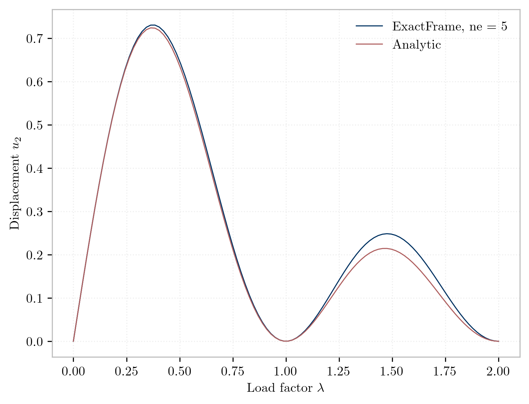
The simulation uses a single load step with uniform meshes of 5 elements for the 2-node and 3-node variants of all formulations investigated by . The solution requires only two iterations for each formulation matching the ideal performance reported by .

The tip displacements for the case λ=1/8\lambda = 1/8 are collected below. The displacements for n=2n=2 -node elements match exactly those reported by for both the natural None, and the logarithmic Init/Incr variants. For n=3n=3 -node elements, the results match the analytic solution up to the reported precision.

Deformed configuration of cantilever beam under two moment magnitudes.
Tip displacements

References  

  • NAFEMS Finite Element Methods & Standards, Abbassian, F., Dawswell, D. J., and Knowles, N. C., Selected Benchmarks for Non-Linear Behavior of 3D-Beams. Glasgow: NAFEMS, Publication NNB, Rev. 1, Oct. 1989. Test NL5.

  • Abaqus NL5 

  • https://classes.engineering.wustl.edu/2009/spring/mase5513/abaqus/docs/v6.6/books/bmk/default.htm?startat=ch02s01ach122.html 

  • https://manuals.dianafea.com/d100/FXpDia/node221.html 

 Elastic Frame
Pinched Shell Cylindrical Problem 
On this page:
End Moment   References  
Finite Rotations
Finite Rotations
A gallery of technical examples currated by the STAIRLab at UC Berkeley.
Code licensed BSD, docs CC BY-NC 4.0
 
Links
Home 
About 
Docs 
Examples
Working with solids 
Nonlinear dynamics 
Basic Statics 
Community
Issues   
Discussions   
Contribute 
STAIRLab
Code copied to clipboard