Frame with Diaphragms
3 min read • 539 wordsA three-dimensional reinforced concrete rigid frame, is subjected to bi-directional earthquake ground motion.
A three-dimensional reinforced concrete rigid frame, is subjected to bi-directional earthquake ground motion.
Modeling
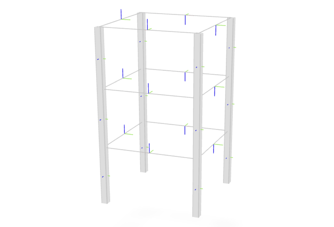
A model of the rigid frame shown in the figure above is created.
The model consists of three stories and one bay in each direction.
We begin by initializing an instance of the
Model
Class:
Beams are modeled using a mixed finite element formulation which accurately accounts for inelasticity (see this example). Inelastic cross sections are constructed as developed in this example to account for material nonlinearities.
Rigid diaphragm multi-point constraints
are defined with the
rigidDiaphragm
method to enforce the rigid in-plane stiffness assumption for the
floors.
Gravity loads are applied to the structure and the 1978 Tabas acceleration records are the uniform earthquake excitations.
Nonlinear beam column elements are used for all members in the structure. The beam sections are elastic while the column sections are discretized by fibers of concrete and steel. Elastic beam column elements may have been used for the beam members; but, it is useful to see that section models other than fiber sections may be used in the nonlinear beam column element.
Analysis
A solution algorithm of type Newton is used for the nonlinear problem.
The integrator for this
analysis will be of type Newmark with a
of 0.25 and a
of 0.5.
The solution algorithm uses a ConvergenceTest which tests convergence on
the norm of the energy increment vector.
Due to the presence of the multi-point constraints (i.e., the rigid diaphragm), a Transformation constraint handler is used.
The analysis is performed by analyzing 2000 steps, each over a time step of 0.01.
Post-Processing
The nodal displacements at nodes 9, 14, and 19 (the retained nodes for
the rigid diaphragms) will be stored in the file node51.out for
post-processing.
The results consist of the file node.out, which contains a line for
every time step. Each line contains the time and the horizontal and
vertical displacements at the diaphragm retained nodes (9, 14 and 19)
i.e. time Dx9 Dy9 Dx14 Dy14 Dx19 Dy19. The horizontal displacement time
history of the first floor diaphragm node 9 is shown in the
figure below. Notice the increase in period after about 10
seconds of earthquake excitation, when the large pulse in the ground
motion propogates through the structure. The displacement profile over
the three stories shows a soft-story mechanism has formed in the first
floor columns. The numerical solution converges even though the drift is
. The inclusion of
effects shows structural
collapse under such large drifts.
References
This model is adapted from Example 5