Finite Rotations
3 min read • 497 wordsThis problem highlights the exceptional accuracy of the ExactFrame formulation for simulating large deformations
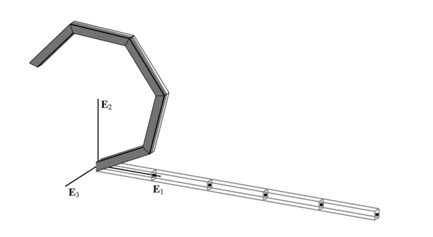
The cantilever beam depicted above is investigated; first under the action of a point moment , then a point force at its free end . The reference curve of the reference configuration is given by .
In order to simulate this problem with OpenSees the
ExactFrame
element
formulation is used. This element requires a shear-deformable section, like
ShearFiber
.
End Moment
When the configuration is expected to remain in the plane. Consequently, the out-of-plane director does not change during deformation so that . This simplification has two important consequences:
-
There is no distinction between a spatially applied moment and a materially applied moment .
-
The rotation becomes vectorial, its variations at different configurations can be added, and the sum of these variations over the course of global equilibrium iterations is equivalent to the logarithmic rotation increment:
In this case, the moment loading can be treated identically for all analyses by simply scaling a constant reference force vector for the node at :
where the reference magnitude varies with , and for different cases causing the cantilever to loop over itself times. The following parameters are used:
Using the
ElasticFrame
section this is added to a
Model
as follows:
model.section("ElasticFrame", tag, E=1e4, G=1e4, A=1, Iy=1e-2, Iz=1e-2, J=1e-2)The analytic solution of the governing boundary value problem is given by:
where parameterizes the rotation .
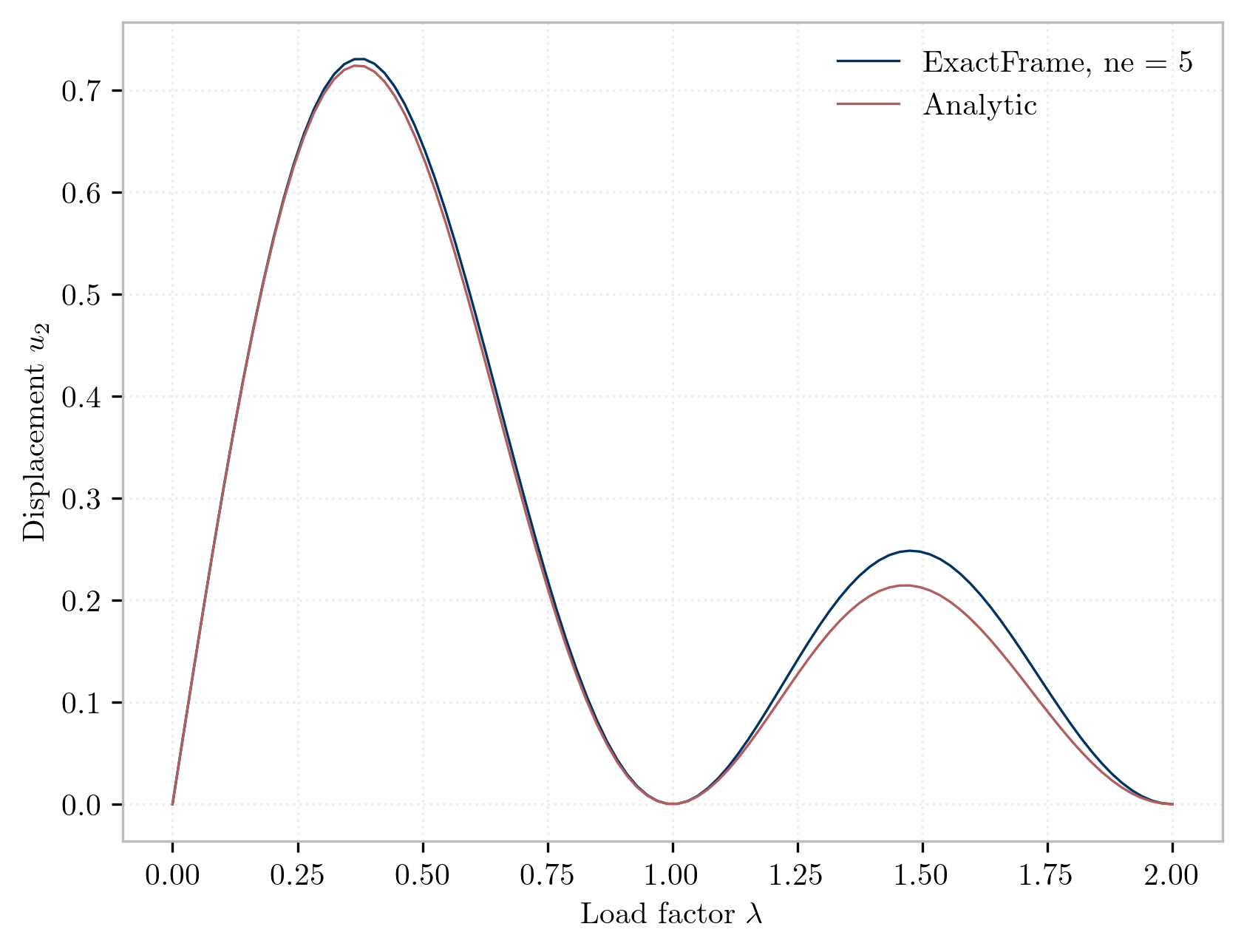
The simulation uses a single load step with uniform meshes of 5 elements for the 2-node and 3-node variants of all formulations investigated by . The solution requires only two iterations for each formulation matching the ideal performance reported by .
The tip displacements for the case
are collected below.
The displacements for
-node elements match exactly those reported by
for both the natural None, and the
logarithmic Init/Incr variants.
For
-node elements, the results match the analytic solution up to the reported precision.

References
- NAFEMS Finite Element Methods & Standards, Abbassian, F., Dawswell, D. J., and Knowles, N. C., Selected Benchmarks for Non-Linear Behavior of 3D-Beams. Glasgow: NAFEMS, Publication NNB, Rev. 1, Oct. 1989. Test NL5.