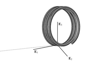
Helical Forms
3 min read • 430 wordsA highly geometrically nonlinear problem is solved with the geometrically exact frame element formulation.

A cantilever beam is subjected to a combined point moment and a point force at its free end . This example is selected to demonstrate the ability of the proposed formulations to naturally accommodate applied moments in various reference frames. It also highlights the accuracy and convergence characteristics of the formulations. Three common variations of this problem are considered with the following properties:
The
ExactFrame
element formulation from OpenSees is employed.
Simple Perturbation
Following , the problem of
plane
flexure with finite rotations is now altered by introducing the point load
in addition to the moment
so as to induce a three-dimensional response.
A uniform mesh of 10, 2-node elements is used, and the reference moment from
this study with
is applied in a single load step.
Because the deformation is no longer plane, each choice of nodal
parameterization essentially equilibriates the moment in a different
coordinate system.
Results are reported in Table
tab:helical-perturb01, where the None/None/None and
Incr/None/Incr variants match the values reported by
for the formulations by
and ,
respectively.
Once again, the application of external isometry or
parameter transformations does not affect the convergence
characteristics of the solution.
Consistent Perturbation
The problem is simulated again, but now the moment is consistently
applied with a spatial orientation.
Formulations whose final residual
moment vector is conjugate to the spatial variations
of the rotation
do not need to be treated differently.
This includes both elements with the None parameter transformation and
transformed elements with the Petrov-Galerkin formulation. For the
simulations with all other elements, a transformation of the nodal force
is necessary, as described in
.
Table
tab:helical-perturb02 lists the tip displacements for the solution.
Oscillating Spiral
To demonstrate the behavior of the proposed formulations under large
rotations, the reference moment value
in is now increased to
with a large out-of-plane force of
.
The model discretization uses 100 two-node elements, and the loading is applied in 200 steps under load factor control.
Figures below show the final deformed shape alongside a plot
of the tip displacement in the direction of the concentrated force.
These results are in agreement with the literature
.
See also